1. Introduction:
Indian Railways is the biggest railway network in the world. Millions of daily commuters and long-distance passengers are catered by Indian Railways. A reliable & safe electrical system in signaling & inside coaches ensures safe and efficient operation of trains and passengers’ safety. The lives of thousands of passengers are at stake. A minor malfunction in signaling system and in electrical facilities inside the coaches like lights, fans, mobile charging points, chilling systems, due to earth leakage/fault will cause a catastrophe which is unimaginable, leading to loss of life of thousands.
Recently Indian railway started premium/ high speed rail operations in selective routes and Bullet Trains also to be introduced in near future. These all needs throughout upgradation of existing Indian railway infrastructure. For that reason new technologies and latest version of measuring, monitoring and control systems will be required. Automated On-line continuous monitoring of various distribution circuits in signaling system and coaches is required which will increase the throughput and safety of trains. The faulty circuits can be detected, located and corrected within 1 hour without shutting down the electrical power distribution system Ungrounded power supplies have the advantage of avoidance of shock & fire and ensure continuity of power to loads in the event of first ground fault. To get the above benefits IEC 60364-4-41 recommends providing an on-line insulation monitoring device to monitor & indicate the first ground fault. Further the first ground fault should be eliminated within the shortest practicable time. Therefore, to identify the faulty feeder as fast as possible and to support maintenance staff online fault location system should be implemented in large complex distribution system. Further the measurement and monitoring technology shall be state of art and reliable and accurate in the presence of AC, DC and AC/DC loads and various electrical noises. Therefore the measuring and monitoring system shall be in conformance
to prevalent International standards for operation in industrial environment. Online insulation monitoring shall conform to IEC 61557-8 and online fault location upto feeder level shall conform to IEC 61557-9. Further the system shall be qualified as per IEC 61326 for EMI/EMC.
Grounded distribution system is also utilized in various non-critical and auxiliary electrical power distribution system in railways. Grounded AC, DC & AC/DC distribution system are used. Rather than waiting for short circuit and catastrophic failures a leakage current monitoring system to monitor the leakage currents due to failure of insulation for advance leakage information shall be provided. Again for using the monitoring system in industrial environment the solution shall be in conformance to IEC 62020.
2. Reference Standards:
1. EN 50122-1: Railway applications – Fixed installations –Electrical safety, earthing and the return circuit
2. EN 50123-1: Railway applications – Fixed installations –D.C. switchgear
3. IEC 61373: Railway applications – Rolling stock equipment
4. EN 45545: Railway applications – Fire protection on railway vehicles
5. EN 50155: Railway applications – Electronic equipment used on rolling stock
6. EN 50121: Railway applications – Electromagnetic compatibility
7. IEC 60364-1: Low voltage electrical installations – Part 1: Fundamental principles, assessment of general characteristics, definitions
8. IEC 60364-4-41: Electrical installations of buildings Part 4-41: Protection for safety-Protection against electric shock
9. IEC 61557-8: Electrical safety in low voltage distribution systems up to 1 000 V a.c. and 1 500 V d.c. – Equipment for testing, measuring or monitoring of protective measures – Part 8: Insulation monitoring devices for IT systems
10. IEC 61557-9: Electrical safety in low voltage distribution systems up to 1 000 V a.c. and 1 500 V d.c. – Equipment for testing, measuring or monitoring of protective measures – Part 9: Equipment for insulation fault location in IT systems
11. IEC 62020-1: Electrical accessories – Residual current monitors (RCMs) – Part 1: RCMs for household and similar uses
3. Solution for signaling system:
Similar to British and European Railways, Indian Railway signaling systems utilize various types of ungrounded low voltage power supplies like 110 V AC/DC, 60 V AC/DC and 24 V AC/DC for the various signal & switching circuits. The circuits include Track Point Switches, Track Motors, Signal Control Relays and Signaling Lamps. The design generally conforms to national and international standards. Most of the cables associated with the above-mentioned circuits are outdoor and run along railway tracks either buried or over ground. They are exposed to the harsh weather and unfavorable environment. These affect their insulation resistance and are subject to deterioration in the harsh environment over a period. This leads to mal-operation and unreliable operation of signal systems, putting the life of thousands of commuters at stake. US, British and European in-house railway standards recommend continuous monitoring of the insulation resistance of these circuits to ensure reliable and safe movement of trains. Further to detect the individual faulty feeder an online fault location system shall be provided.
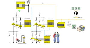
Each galvanically isolated separate supply source will consist of an online insulation monitor connected near to the source main bus. Individual feeders will be installed with special highly sensitive sensors over the complete feeder wires along with multichannel earth fault detector to which the sensors shall be connected for identifying automatically the faulty feeder without shutting down the distribution system. After identifying the faulty feeder, with the help of portable handheld fault locator exact location of earth fault can be identified. Portable devices also trace the signal injected by the insulation monitoring device.
A typical sketch of the solution is shown below.
4. Solution for Railway Coaches:
An ungrounded power supply also used inside coaches’ electrical systems to have same benefit.
a) Prevents fire due to insulation leakage.
b) Prevents fatal electrical shock to the passengers.
c) Availability of loads.
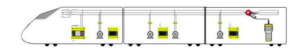
The main incomer power supply to individual coaches is either 800 V 3 phases 3 wire ungrounded or 800 V 3 phase 4 wire grounded system depending on the design requirement of RDSO. Which is later being stepdown to 415V 3phase, 230 & 110V single phase as per the load requirement inside the coaches. Each and every relay should have MODBUS RTU communication system to directly communicate with HMI system.
Each galvanically isolated separate supply source will consist of an online insulation monitor connected near to the source main bus. It will measure the insulation resistance of the complete connected distribution system up to individual loads and provides alarm whenever the earth fault insulation resistance is below set limits. The maintenance staff can plan for fault identification and repair.
Portable handheld fault evaluator suitable up to 800V AC system can be used to localization of fault during running condition of the train or at loco shed.
A typical sketch of the solution is shown below.
5. Electrical safety in Railway Tunnels:
Train routes in mountainous landscapes lead across a sequence of tunnels and bridges. The route operator must be prepared for a train accident in a tunnel. Along the route, fire brigades and Technical Relief Services are equipped for assistance in case of catastrophe. To support the rescue concept, hydrants and emergency power supply points are installed in the tunnels. Rescue teams thus have quicker access to water and electrical energy in sufficient quantities. According to the guideline 95401, in Germany the power supply has to be designed as an ungrounded system.
Securing a functioning power supply for rescue teams even in case of catastrophe: So that rescue teams can rely on a functioning power supply in the event of a catastrophe, continuous insulation monitoring is required. Critical installation conditions are reported to the supervising system in a timely manner.
Fast localisation of insulation faults: Even in the case of extensive routes, insulation faults can be allocated to the individual tunnel sections when using insulation fault location systems as like signaling system. A further advantage is: They find insulation faults during ongoing operations, without cable disconnection.
Case study
1. Bender offered Solution in Signaling System:
BENDER, the world leader in this technology provides universal and customized solutions in on-line monitoring insulation resistance and fault location in ungrounded AC & DC electrical systems. Suitable for signaling system.
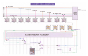
BENDER with its large amount of experience and R&D efforts over more than 70 years provide ingenious solution for on-line insulation monitoring and fault location up to individual feeder level in AC/DC systems in presence of various industrial electrical noises without spurious operation and indications (EMI/EMC qualified). Bender Insulation Monitoring Device conforms to IEC 61557-8, Fault location system conforms to IEC 61557-9 and EMC qualified as per IEC 61326. The implementation schematic in Indian Railway Signaling is below
As shown in the figure above the insulation monitoring scheme for ungrounded system consists of Insulation Monitor iso685 connected to the main ungrounded distribution source bus. The insulation monitor may derive its power from the same system and it can accept wide range of power input both AC & DC from 0 to 600 Volts. The insulation monitor injects a special Bender patented bidirectional signal into the system with respect to earth and will on-line monitor the insulation of the complete ungrounded distribution system of all feeders including loads supplied from same source with respect to earth and indicate the value in the range of 1 Kohm – 10 Mohm. It will generate an alarm in case the insulation of the complete distribution system falls below the set value.
Typical set value for alarm is about 50 to 100 ohms/ Volt of the system voltage and it has another unique feature that in can generate two different alarms indicating gradual de-gradation of insulation resistance. We can define 1st alarm as pre-alarm and 2nd one as critical alarm. For safe running of the system one can set the pre alarm value at 200 ohm/Volt and critical alarm value at 100 ohm /volt
which is in line with IEC (e.g. for system voltage 110 V, the pre-alarm setting is 40 Kohm and critical alarm is 20Kohm). The Operation & Maintenance staff comes to know in advance that there is an insulation fault somewhere in the signaling distribution system with indication of pre-alarm and as per their convenience they can plan their maintenance activity.
The main power supply is distributed into various feeders as per the requirement of the station signaling system. To locate the actual faulty feeders, each of the load feeders will be installed with specialized highly sensitive Bender patented core balance Current Transformers (CT), with sensitivity of 5 mA. All CT’s will be connected to required nos. of 12 channel evaluators EDS440.
The EDS440 may draw its power from the main distribution system. In case of insulation fault (lower than both the alarm settings) in any feeder , the iso685 will first give visual alarm & then it will inject a test current (adjustable by user) in the distribution system with peak value limited to 25 mA.
The peak value of 25 mA is much below the dropout current of 40 mA of relays used in railway signal circuits and will not interfere with the functioning of the system. This test current will pass through the faulty feeder via earth and the corresponding faulty feeder CT will detect and indicate on-line the fault in the corresponding channel of EDS440.
Iso685 & EDS-440 also interconnected with 2-wire RS 485 interface hence iso685 also indicate the channel no. of the faulty feeder. Further with the help of Bender make portable fault evaluator EDS 3090 identification of the exact faulty
component also possible. A Bender make gateway may also be used to indicate the faulty feeder in the control room on a PC.
In this way complete system will be monitored online 24×7, Which is very much required for railway signaling system.
Bender Model BOQ for signaling system application:
| Sr. No. | Item description | Model | Remarks |
| 1 | Online insulation Monitoring Device | Iso685-S-P+FP200/ iso685-D-P | 1 no. per source |
| 2 | 12 channel Earth Fault Evaluator | EDS440-L-4 | Depends on number of feeders |
| 3 | Core Balance Current Transformer | WS20X30 | Depends on number of feeders |
| 4 | Portable Fault locator | EDS3096-PG | 1 no. per RRI |
2. Bender Solution in Coaches:
BENDER with its large amount of experience and R&D efforts over more than 70 years provide ingenious solution for on-line insulation monitoring and fault location up to individual feeder level in AC/DC systems in presence of various industrial electrical noises without spurious operation and indications (EMI/EMC qualified). Bender Insulation Monitoring Device conforms to IEC 61557-8, and EMC qualified as per IEC 61326. The implementation schematic in Indian Railway Coaches is below.
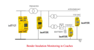
Bender manufactured Insulation Monitor relay suitable to monitor the insulation of 800 V 3phase , 415V 3-phase, 230 Volt, 110 Volt single phase AC power circuits & 24V DC emergency light circuits in coaches and thereby generating alarm whenever the insulation value with respect to earth decreased below the set value without tripping the circuit. thereby ensuring passenger safety and protection of assets.
Bender Model BOQ for Coach application
| Sr. No. | Item description | Model | Remarks |
| 1 | Online Insulation Monitoring Device for 800 V AC | isoHV425+AGH420 | 1 no. per source |
| 2 | Online Insulation Monitoring Device for 415V AC, 230AC, 110V, 24VDC | EIso415R-2 | D1 No. Per source |
| 3 | Residual Current Monitoring Device for 750V AC 3 Phase | RCM410R-2 & CTAC70 | For 750V3 Phase 4 wire system |
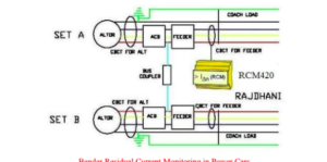
Bender also manufactures residual current relay with CBCT to monitor the earth leakage current of 800VAC 3-phase 4-wire earthed/grounded supply to coaches and thereby generating alarm whenever the leakage current exceeded the set value ensuring safety of passengers and railway coach assets. This is in conformance to IEC 62020-1.
 Author:
Mahesh C. Yadav,
Director,
Indotech Global System,
Ex. IRSSE, Chartered Engineers(I), Retired Dy Chief Signal & Telecommunication Engineer (RE/IR)